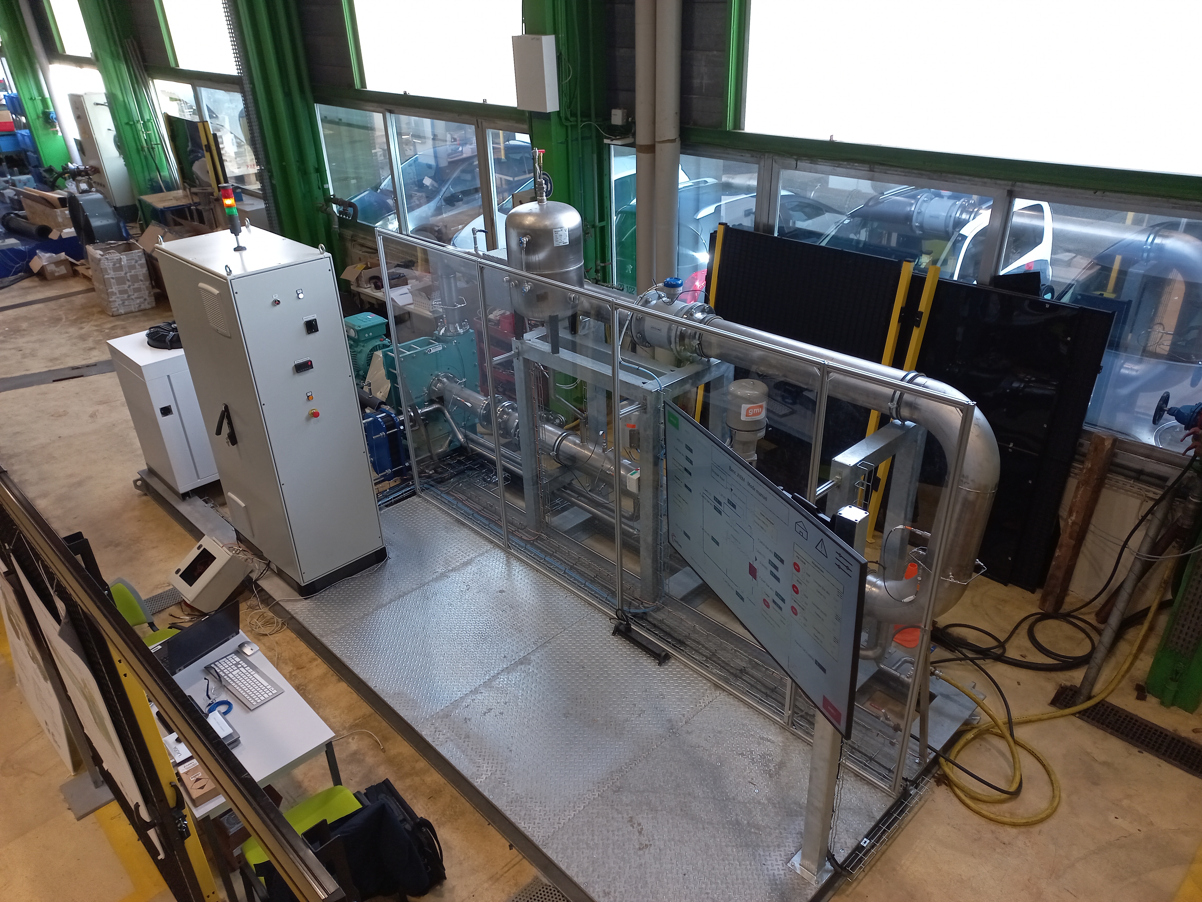
Fluidic loop
Mahussi Datongnon (Inria) · Hubert Lejeune (CETIM) · Jus Yoann (CETIM)
Summary
The digital twin of the fluidic loop system is designed to provide monitoring and decision-support capabilities. The physical system consists of a closed hydraulic loop equipped with a centrifugal pump, a heat exchanger and several regulation components/actuators. Its function is to deliver the flow rate, pressure and/or temperature requested by the operator.
The digital twin processes this data through a collection infrastructure to feed a set of hybrid models. The core of the system rests on a thermo-hydraulic physical model capable of simulating fluid behaviour as a function of operating conditions. This model is complemented by data-driven models enabling improvement of specific functions such as anomaly detection or parameter estimation.
The main functions provided by the digital twin are:
- Operating condition monitoring from sensor data and simulation.
- Cavitation detection, identifying the risk of cavitation associated with a future operating point in the system.
- Virtual sensor enabling flow estimation in the event of sensor failure.
- Energy analysis, through simulation of alternative operating scenarios (e.g. cooling strategies).
- Divergence detection, based on continuous comparison between real measurements and simulated results.
When significant deviations are detected, the data-driven models identify the parameters responsible for the deviations and estimate their correction, enabling adjustment of the physical model. This adaptation loop ensures fidelity of the digital twin is maintained despite evolution of the real system.
Functional Description
Users
- A supervision operator - monitors system variables, consults indicators provided by the digital twin and makes operational decisions (cooling management). Uses cavitation detection features to assess whether a future operating point is likely to cause cavitation at the pump, suction valve or regulation valve.
- A development engineer (modelling / simulation) - designs, calibrates and maintains the thermo-hydraulic physical model and its integration into the digital twin.
- A researcher / R&D expert - uses the digital twin as an experimental platform to test hybridization strategies, model adaptation and fidelity improvement. Develops, trains and validates data-driven models (fault localisation and estimation) used for model recalibration.
- An automated system (via PLC) - executes control actions (pump adjustment, valve opening, cooling activation) on request from the operator.
Functional Requirements
-
Describe + Interact · A supervision operator wants to visualise key variables (pressure, flow rate, temperature) and the system state estimated by the digital twin in order to understand process behaviour and make informed operational decisions in continuous operation. Metric: refresh frequency = 1 Hz.
-
Diagnose · A researcher / R&D expert wants to detect and analyse divergences between real measurements and digital twin results in order to identify model limitations, potential faults or recalibration needs. Metric: analysis frequency = 1/60 Hz, simulation-reality divergence ≥ threshold.
-
Optimise + Predict · A supervision operator wants to compare several cooling strategies (FAST, SLOW, SMART) in order to select the best trade-off between cooling duration and energy consumption before implementation. Metric: cooling time for each scenario, energy consumed for each scenario.
-
Secure + Diagnose · A supervision operator wants to evaluate the cavitation risk associated with a future operating point in order to prevent damage to the pump, suction valve and regulation valve before applying new setpoints.
-
Describe + Secure · A supervision operator wants to continue having access to critical variables through a virtual sensor in the event of flow sensor loss or failure in order to maintain process monitoring. Triggered as soon as flow information is not available.
-
Optimise + Diagnose · A researcher / R&D expert wants to train, validate and evaluate data-driven models for fault localisation and estimation in order to improve the adaptation and recalibration capabilities of the digital twin. Metric: localisation accuracy ≥ threshold, estimation error ≤ threshold.
-
Control · An automated system (via PLC) wants to execute commands issued by the operator (pump adjustment, valve control, cooling management) in order to apply the selected setpoints.
Digital Twin Characterisation
Grid based on the unified framework by Gil et al. (2024) - 21 characteristics.
MC1 - System under study
The system under study is an instrumented thermo-hydraulic fluidic loop, used to control and observe process variables such as pressure, flow rate and temperature. It is composed of a set of interconnected physical components including a pump, a regulation valve and a cooling system, forming a closed fluid circulation circuit.
The system operates in an industrial environment comprising:
- a programmable controller (Beckhoff PLC) driving the actuators,
- an IT infrastructure (industrial PC, communication network),
- human operators responsible for supervision and maintenance.
The agents involved include:
- supervision operators, who monitor system variables,
- engineers and maintainers, who analyse performance and intervene in case of deviation,
- an automated system (PLC), which executes commands.
MC2 - Physical Acting Components
The physical action components are the actuators enabling modification of the fluidic loop behaviour:
- Pump (speed control) - adjusts the fluid flow rate in the loop.
- Regulation valve - controls the opening to modulate pressure and flow rate.
- Cooling system (on/off valve) - regulates fluid temperature by activating or deactivating cooling.
These actuators are driven via the Beckhoff PLC, which executes setpoints from the control system.
MC3 - Physical sensing components
The system is equipped with several sensors measuring the process state and providing data to the digital twin:
- Pressure sensors
- Temperature sensors
- Pump speed sensor
- Flow rate sensor
Sensor data is transmitted to the digital system via the PLC and industrial communication infrastructure (OPC UA, MQTT), feeding the digital twin models.
MC4 - Physical-to-Virtual Interaction
The interaction from the physical system to the digital twin relies on continuous sensor data acquisition, enabling the system state to be reflected in the virtual environment.
Transmitted data includes:
- Process variables: pressure (multi-point), temperature, flow rate (if available),
- Control variables: pump speed, regulation valve position, cooling system state
On the technical side, the transmission chain is structured in several levels:
-
Local collection (plant level):
- Sensors are connected to the Beckhoff PLC and the OPC UA server,
- Data is structured according to industrial standards embedded in the PLC.
-
Industrial communication:
- Use of the OPC UA protocol for standardised and interoperable industrial data exchange.
-
Ingestion and processing:
- Data storage in a database, ensuring persistence and historical exploitation.
-
Frequency and volume: Acquisition at a frequency of 1 Hz
MC5 - Virtual-to-Physical Interaction
The interaction from the digital twin to the physical system relies on the transmission of commands and operational recommendations aimed at dynamically adjusting fluidic loop behaviour.
Transmitted data includes:
- adjustment of pump speed,
- modification of regulation valve opening,
- process cooling control by selecting a thermal scenario (FAST, SLOW or SMART) determining cooling system activation conditions during the cooling phase.
- FAST scenario: the cooling system is engaged at full power from the start of the cooling phase and remains active until the target temperature is reached. This scenario prioritises cooling speed.
- SLOW scenario: no active cooling is implemented. Temperature decrease relies solely on the loop’s natural thermal losses. This scenario minimises energy consumption at the expense of cooling time.
- SMART scenario: an intermediate approach combining passive and active cooling. Initially, the temperature decreases naturally. When the loop temperature reaches the midpoint between the initial and target temperature, the cooling system is activated to complete the cooling. This scenario aims for a balance between speed and energy consumption.
On the technical side, the transmission chain is organised as follows:
- Decisions are generated from the digital twin services (simulation, data-driven models).
- Commands are transmitted to the Beckhoff PLC.
MC6 - Digital Twin Services
The digital twin provides a set of operational and analytical services for monitoring, diagnosis and optimisation of the fluidic system. These services rely on the joint use of physical and data-driven models.
The main services are:
-
Monitoring and visualisation: Provides a representation of system variables (pressure, temperature, flow rate).
-
Cavitation detection: Evaluates the cavitation risk associated with a future operating point to prevent damage to the pump, suction valve and regulation valve before applying new setpoints.
-
Virtual sensor: Estimates flow rate in the event of sensor failure from the physical model and other available data.
-
Energy analysis: Compares several cooling strategies (FAST, SLOW, SMART) to select the best trade-off between cooling duration and energy consumption before implementation.
-
Divergence detection: Continuously compares simulated results with real measurements to identify significant deviations between the physical system and the digital twin.
-
Divergence cause diagnosis: Uses data-driven models to identify the physical model parameters responsible for observed deviations.
-
Parameter estimation and update: Calculates corrected parameter values to improve digital twin fidelity and maintain its alignment with the real system.
MC7 - Twinning Time-scale
The digital twin operates across several complementary time scales, adapted to different services and uses.
-
Run-time Sensor data is acquired and transmitted at a frequency of 1 Hz
-
Scenario simulation From 5 s to 45 s depending on the chosen scenario
-
Inductive models
- Training dataset generation: approximately 560 s
- Localisation and estimation of a parameter to update: approximately 35 s
MC8 - Multiplicities
No digital sub-twin.
MC9 - Life-cycle Stages
The digital twin covers mainly the operation, maintenance and partially design/validation phases of the fluidic system.
-
Design / validation (partial) The digital twin is used to simulate different operating scenarios (parameter variation, cooling strategies), enabling testing and validation of design or configuration choices without direct intervention on the physical system.
-
Operation (main phase) The core use of the digital twin is in operation, with:
- system variable monitoring,
- cavitation and anomaly detection,
- virtual sensor to compensate for sensor failures,
- performance analysis (energy, hydraulic behaviour).
-
Maintenance The digital twin plays an active role in maintenance by:
- detecting divergences between the model and the real system,
- identifying drift causes (degraded parameters),
- facilitating diagnosis.
-
Continuous evolution (extended lifecycle) Through hybridization, the digital twin supports a continuous improvement logic, with:
- model parameter updates,
- adaptation to real system evolution.
MC10 - Digital Twin Models and Data
The digital twin relies on a hybrid architecture combining physical and data-driven models, fed by data flows from the real system and synthetic data generated in simulation.
Models used
-
Physical models (deductive) The 1D thermo-hydraulic model (implemented in Simcenter Flomaster), used to simulate fluidic system behaviour. Two levels of complexity are used:
- a hydraulic model, for fast calculations,
- a thermo-hydraulic model, integrating thermal effects. These models calculate process variables (pressure, flow rate, temperature) as a function of physical parameters and control inputs.
-
Data-driven models (inductive) Two types of learning models complement the physical model:
- a fault localisation model (decision tree), identifying parameters responsible for observed deviations between simulation and reality,
- a parameter estimation model (LS-SVR), enabling inference of corrected values for these parameters.
-
Hybrid architecture
- the physical model produces a reference simulation,
- the data-driven models analyse deviations and adjust parameters,
- the simulation model parameters are updated to remain aligned with the real system.
Data
-
Input data: Valve opening, Pump speed, Process temperature
-
Physical model parameters: friction loss coefficients in pipe sections, tank pressure
-
Output data: Pump inlet pressure, Pump outlet pressure, Simulated flow rate, Heat exchanger inlet pressure, Heat exchanger outlet pressure, Temperature
-
Training data: The data-driven models are trained on datasets combining synthetic data, generated by simulation by varying:
- input data,
- physical parameters.
MC11 - Tooling and Enablers
The digital twin relies on an ecosystem of industrial and simulation tools.
Industrial and edge tools
-
Beckhoff PLC (TwinCAT) Drives actuators, acquires sensor data and executes control logic.
-
Industrial PC (edge computing) Enables local execution of latency-sensitive services and hosts digital twin components.
-
TwinCAT ADS (API) Library used for bidirectional communication between digital applications and the PLC (variable read/write).
Simulation and interoperability
-
Simcenter Flomaster Thermo-hydraulic simulation tool used to develop physical system models.
-
FMPy (FMU execution) Framework for executing models exported in FMU (Functional Mock-up Unit) format.
-
FMU / FMI (standard) Interoperability standard for integrating multi-physics models in distributed environments.
Communication and protocols
- OPC UA Industrial standard for data exchange with the PLC and equipment.
User interface
- Web application
Visualisation and interaction interface enabling:
- system variable supervision,
- access to simulation and analysis results,
- interaction with digital twin services.
MC12 - Digital Twin Constellation
Service-oriented architecture: sensors → PLC (collection and control) → industrial communication (OPC UA) → database → digital twin services (FMU simulation, data-driven models, diagnostics) → user interface and/or PLC feedback.
Data-driven models complement the physical model by analysing deviations and adjusting parameters at runtime.
Feedback loop: digital twin services → supervisor setpoints → communication to PLC (TwinCAT ADS) → actuators (pump, valve, cooling) → modification of physical state → new sensor measurements → digital twin re-feeding.
MC13 - Twinning Process and Digital Twin Evolution
Incremental and progressive approach:
-
Step 1 - Initial physical modelling Development of a 1D hydraulic and thermo-hydraulic 1D model of the system (simulation) with initial calibration based on experimental data.
-
Step 2 - Connection to the real system Integration of sensors and PLC enabling data acquisition and model synchronisation (observation + simulation mode).
-
Step 3 - Basic service deployment Implementation of initial digital twin features: simulation, visualisation, cavitation detection, virtual sensor.
-
Step 4 - Introduction of hybridization Addition of data-driven models trained on simulated and real data to:
- detect divergences,
- identify responsible parameters,
- estimate their corrections.
-
Step 5 - Continuous adaptation loop Integration of models into a closed loop enabling physical model parameter adjustment at runtime.
Planned evolution:
- transition to active learning approaches,
- improvement of model fidelity (physical refinement).
MC14 - Fidelity and Validity Considerations
The digital twin reproduces fluidic system behaviour with a level of fidelity depending on both the physical model and hybridization mechanisms.
-
Physical model accuracy The 1D thermo-hydraulic model captures the overall system dynamics (pressure, flow rate, temperature) with satisfactory accuracy under nominal conditions.
-
Calibration and validation The model is initially calibrated from experimental data obtained from the real system.
-
Dynamic adaptation (hybridization) Fidelity is maintained over time through:
- divergence detection between simulation and measurements,
- use of data-driven models to adjust certain physical model parameters. This compensates for unmodelled effects (wear, losses, unforeseen conditions).
-
Limitation management
- The virtual sensor enables estimation of missing variables.
- Validation mechanisms prevent application of inconsistent corrections.
MC15 - Digital Twin Technical Connection
-
Physical level → edge Communication between sensors/actuators and the Beckhoff PLC via internal industrial buses and I/O interfaces.
-
PLC level → digital systems
- OPC UA: main protocol for standardised industrial data exchange.
-
Feedback loop (virtual → physical)
- Communication to the PLC via TwinCAT ADS to apply setpoints to actuators.
MC16 - Digital Twin Hosting/Deployment
Combines local execution and cloud services:
-
Edge level (local industrial)
- Industrial PC hosting digital twin components for low-latency processing.
- Direct communication with PLC via TwinCAT ADS for interactions.
-
Storage level
- Relational database
-
Application level
- Web interface accessible remotely for supervision, visualisation and interaction with the digital twin.
MC17 - Insights and decision-making
-
System state visualisation
- Display of variables (pressure, flow rate, temperature)
-
Detection and alerts
- Alert in case of cavitation risk
- Reporting of significant deviations between the real system and the model (divergence)
-
Diagnostics
- Identification of parameters responsible for drift
-
Predictive analysis and scenarios
- Simulation of alternative scenarios (what-if) of operating points to anticipate cavitation
- Evaluation of loop cooling strategies
MC18 - Horizontal integration
-
Connection with industrial systems
- Integration with the Beckhoff PLC for control and acquisition.
- Indirect exchange with supervision systems via standard protocols (OPC UA).
-
Connection with information systems (IT)
- Data storage and exploitation in a database, which can be shared with other applications (analytics, reporting).
MC19 - Data ownership and privacy
CETIM owns both the test bench (located in Nantes, on its premises) and the associated data. The conditions for data sharing and dissemination, as well as data format definition, are currently being studied.
MC20 - Standardisation
-
FMI (Functional Mock-up Interface) Standard used for model export and integration as FMU (Functional Mock-up Units), enabling their execution in different environments (via FMPy).
-
OPC UA (Open Platform Communications Unified Architecture) Industrial standard for data exchange between the PLC and digital systems, ensuring interoperability and vendor independence.
MC21 - Security and Safety Considerations
Scientific and Technical Challenges
Model hybridization in digital twins
The digital twin of the fluidic loop highlights the need to combine physical (deductive) models and data-driven (inductive) models to meet the requirements of modern industrial systems. In practice, the physical model provides a robust explanatory structure, while learning models capture unmodelled phenomena (losses, degradations, noise). The scientific challenge lies in defining coherent and generalisable hybridization modes, enabling structured interaction between these models.
Resources
References
- Poster - EDT · UC05 · JNEM Thermo-hydraulic Loop - Yoann Jus, CETIM
Ongoing Theses
- Model Hybridization in Digital Twins for Mechanical Engineering - Mahussi Datongnon, Inria (PC1)